
AIM Text
- The SDF provides a final approach course similar to that of the ILS localizer. It does not provide glide slope information. A clear understanding of the ILS localizer and the additional factors listed below completely describe the operational characteristics and use of the SDF.
- The SDF transmits signals within the range of 108.10 to 111.95 MHz.
- The approach techniques and procedures used in an SDF instrument approach are essentially the same as those employed in executing a standard localizer approach except the SDF course may not be aligned with the runway and the course may be wider, resulting in less precision.
- Usable off-course indications are limited to 35 degrees either side of the course centerline. Instrument indications received beyond 35 degrees should be disregarded.
- The SDF antenna may be offset from the runway centerline. Because of this, the angle of convergence between the final approach course and the runway bearing should be determined by reference to the instrument approach procedure chart. This angle is generally not more than 3 degrees. However, it should be noted that inasmuch as the approach course originates at the antenna site, an approach which is continued beyond the runway threshold will lead the aircraft to the SDF offset position rather than along the runway centerline.
- The SDF signal is fixed at either 6 degrees or 12 degrees as necessary to provide maximum flyability and optimum course quality.
- Identification consists of a three-letter identifier transmitted in Morse Code on the SDF frequency. The appropriate instrument approach chart will indicate the identifier used at a particular airport.
FIG 1-1-8
FAA Instrument Landing Systems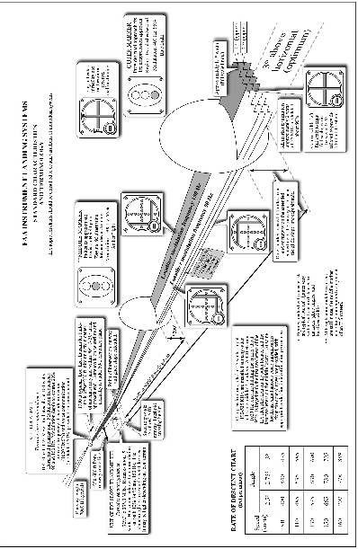
Source: FAA Aeronautical Information Manual · current edition · paragraph 1-1-10.
The short answer
This AIM section describes the Simplified Directional Facility (SDF), which provides a final approach course similar to an ILS localizer but no glide slope. As FAA advisory guidance, it explains that the SDF course may not align with the runway, may be wider (less precise), transmits between 108.10 and 111.95 MHz, and is identified by a three-letter Morse Code identifier, supporting IFR approaches under 14 CFR 91.175.
Research Notes
Common Questions
Does an SDF give glide slope guidance?
No. The AIM states the SDF provides a final approach course similar to that of the ILS localizer but does not provide glide slope information. Techniques are essentially the same as a standard localizer approach, except the SDF course may not be aligned with the runway and may be wider, resulting in less precision.
How wide is the SDF course and how far off-course are indications usable?
Per the AIM, the SDF signal is fixed at either 6 degrees or 12 degrees as necessary to provide maximum flyability and optimum course quality. Usable off-course indications are limited to 35 degrees either side of the course centerline; indications received beyond 35 degrees should be disregarded.
Why might continuing an SDF approach past the threshold lead me off the runway?
The AIM explains that the SDF antenna may be offset from the runway centerline, with a convergence angle generally not more than 3 degrees that should be determined from the approach chart. Because the course originates at the antenna site, an approach continued beyond the runway threshold leads the aircraft to the SDF offset position rather than along the runway centerline.